|
The
68681 Board |
| Jumpers |
| |
|
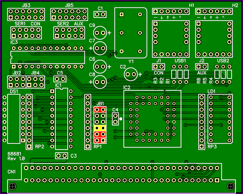
Default settings: |
|
IC2 = MC68681 |
place Jumpers as
shown in RED below |
|
IC2 = XR68C681 |
place Jumpers as
shown in RED & YELLOW below |
|
 |
| |
|
J1 U1PWR - USB1 Power |
| |
|
This Jumper
determines if 5V power for the whole system is derived
from the host system attached to USB1. |
| |
|
J1 open - USB
power disabled |
|
J1 short - USB
power enabled |
| |
|
J2 U2PWR - USB2 Power |
| |
|
This Jumper
determines if 5V power for the whole system is derived
from the host system attached to USB2. |
| |
|
J2 open - USB
power disabled |
|
J2 short - USB
power enabled |
| |
| Note: |
|
Modern computer
USB ports supply 5V DC and typically allow a maximum
current draw of 500mA which
means the maximum power output is only 2.5 Watts. If you have
a large
Mega-68000 Computer System DO NOT attempt to power
it via USB - leave J1 and J2 open and use an external
power supply. |
| |
| JB1 STXSF -
Serial TX & Software Features |
| |
|
The following JB1
links control serial data transmission from the board: |
| |
|
1-2 short |
USB1
(CON) TX enabled |
|
3-4 short |
USB2
(AUX) TX enabled |
|
| |
|
The remaining JB1
links control software features within System ROM V2.0x
as follows: |
| |
|
5-6 short |
115K baud DUART (XR68C681) support enabled |
|
7-8 short |
N/A |
|
9-10 short |
ROM diagnostics
(Slow Boot)
enabled |
|
11-12
short |
ACRTC
graphics test
enabled |
|
|
| |
|
JB2 & JB3 |
| |
|
These Jumper
Blocks determine where the RS-232 TX, RX, & Flow Control
signals go on the SER1 CON Port. |
| Refer to the
schematic for more detail. |
| |
| Note: |
| When using
USB1 these Jumper Blocks serve no purpose. |
| |
| JB4 & JB5 |
| |
|
These Jumper
Blocks determine where the RS-232 TX, RX, & Flow Control
signals go on the SER2 AUX Port. |
| Refer to the
schematic for more detail. |
| |
| Note: |
| When using
USB2 these Jumper Blocks serve no purpose. |
| |
| |